Skip to Content

Category Archives: TECH

GPI 2.0

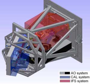
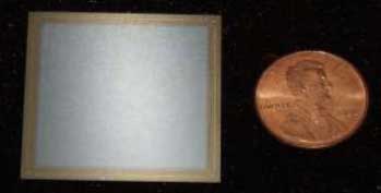
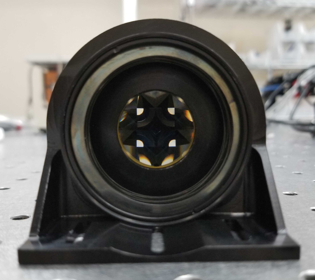
The upgrades that will result in GPI 2.0 include state of the art optical and software systems.

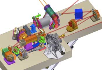
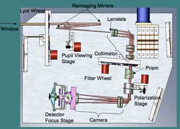
The schematic below shows the improvements that will be made to GPI’s technology before the new-and-improved instrument makes its way to Gemini North in Hawai’i

The upgrades to GPI 2.0 include more advanced optical elements.

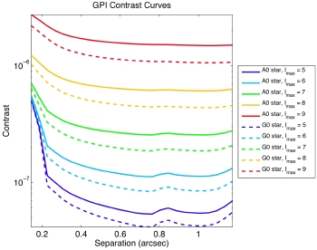
Click to see full detail.

For more details on specs of GPI 2.0, click here.

0 0 Continue Reading →

GPI Contrast Curves

These are 5-sigma contrast levels achievable with different wavefront sensor sensitivity levels and one-hour integrations. The simulations are done over two R = 45 spectral channels, where the central wavelength is 1.65 microns and SDI has been applied over the 1.579-1.624 micron region. The dramatic improvement in contrast up to about 0.2 arcsec separation is due to speckle suppression. Click on the image to magnify.


These are 5-sigma contrast levels achievable with different wavefront sensor sensitivity levels and one-hour integrations. The simulations are done over two R = 45 spectral channels, where the central wavelength is 1.65 microns and SDI has been applied over the 1.579-1.624 micron region. The dramatic improvement in contrast up to about 0.2 arcsec separation is due to speckle suppression. Click on the image to magnify.


The combination of ADI (angular differential imaging) and SDI (spectral differential imaging) speckle suppression techniques greatly improves the contrast achievable with GPI. Contrast depends strongly on the performance of the wavefront sensor: for a star with a given I magnitude, a wavefront sensor that can lock on I = 9 stars will perform much better than one that requires I = 5 stars. Contrast also depends on the spectral type of the target star: since H band data will be taken, later spectral types will be brighter in H band than earlier spectral types for the same I magnitude.

0 0 Continue Reading →

The Gemini South Telescope

GPI is mounted on a side port of the instrument support structure of the Gemini South telescope. More information about Gemini Telescope may be found here

The Gemini Telescopes are located in Hawaii and in Chile. Both telescopes have primary mirrors that are 8 meters in diameter (Photo: Paul Kalas)

The Gemini Telescopes are located in Hawaii and in Chile. Both telescopes have primary mirrors that are 8 meters in diameter (Photo: Paul Kalas)

The Gemini Observatory is operated by the Association of Universities for Research in Astronomy, Inc., under a cooperative agreement with the NSF on behalf of the Gemini partnership: the National Science Foundation (United States), the National Research Council (Canada), CONICYT (Chile), the Australian Research Council (Australia), CNPq (Brazil), and SECYT (Argentina).

Geminipartners

The Gemini Observatory is operated by the Association of Universities for Research in Astronomy, Inc., under a cooperative agreement with the NSF on behalf of the Gemini partnership: the National Science Foundation (United States), the National Research Council (Canada), CONICYT (Chile), the Australian Research Council (Australia), CNPq (Brazil), and SECYT (Argentina).


Gemini’s Mission

To advance our knowledge of the Universe by providing the international Gemini Community with forefront access to the entire sky.”


0 5 Continue Reading →

GPI Opto-Mechanical Super Structure

The GPI super structure is responsible for housing and keeping aligned several sophisticated subsystems, each weighing a few hundred kilograms. While isolating these subsystems from the relatively high vibrations from both the telescope structure and GPI’s own two hundred kilograms of electronics and cooling systems, it must control relative flexure to less than the 100-micron level over all operational orientations and provide the necessary stability to the precision IR interferometer. Additionally, Gemini imposes strict mass, centre of mass, space envelope and power usage and dissipation limits. The mechanical structure is a pair of cantilevered truss structures: one for the non-flexure sensitive components and overall enclosure (external frame structure, EFS), and the second the opto-mechanical components (flexure sensitive structure FSS). Each subsystem is kinematically constrained with three bipod flexure truss assemblies.

GPI's opto-mechanical super structure (OMSS). The diagram maps the locations of the AO, CAL, and coronagraph units. The plate on the right mounts to the Gemini instrument support structure.

GPI’s opto-mechanical super structure (OMSS). The diagram maps the locations of the AO, CAL, and coronagraph units. The plate on the right mounts to the Gemini instrument support structure.

The three main subsystems are the AO relay (AO), the calibration system (CAL) and the integral field spectrograph (IFS). The AO optics will be mounted on a custom cast-aluminum optical bench, with the optics all in-plane. Individual optics will be superpolished to have less than 1 nm of mid-spatial-frequency wavefront error, supported in extremely stiff mounts to minimize vibration and flexure. The whole instrument will be surrounded in a better than Class-1000 enclosure to control the accumulation of dust particles thatwould scatter starlight and hide planets. The bulk of the electronics are mounted in cabinets outside this enclosure, cooled by chilled glycol provided by the observatory. With the combination of the very stiff mechanical design and open loop control of tip and tilt on 5 fold mirrors, the OMSS will maintain the 1-2 cm optical beam fixed to less than 1% of the its diameter throughput the entire optical path.

0 6 Continue Reading →

GPI Calibration Interferometer

Unsensed and uncorrected non-common path wave front errors will set the limit for achievable contrast for a ground-based AO system.

These errors are particularly vexing due to their temporal evolution. If they were perfectly static, they could be measured once and then subsequently removed in post processing. If they were perfectly random, they would average out to a smooth floor over long integrations. Non-common path errors that limit contrast tend to evolve over times scales of a few minutes to 10’s of minutes and therefore must be sensed and corrected during a science observation. The main goal of the calibration system for GPI is to sense these wave front errors at the science wavelength and coronagraph FPM location and provide this measurement to the AO system so that they may be corrected.

The GPI calibration unit has thirteen mechanisms with 28 degrees of freedom to configure the calibration system and compensate for dimensional changes due to structural flexure, mechanical disturbances, and thermal changes. In addition to these there are four mechanisms associated with thermal control.

The GPI calibration unit has thirteen mechanisms with 28 degrees of freedom to configure the calibration system and compensate for dimensional changes due to structural flexure, mechanical disturbances, and thermal changes. In addition to these there are four mechanisms associated with thermal control.

0 1 Continue Reading →

GPI Science Instrument

The science instrument for GPI is an integral field spectrograph based on a lenslet array. The integral field nature of the instrument allows for a full mapping of the focal plane at coarse spectral resolution. With such a data cube, p within the PSF such as residual speckles can be suppressed. Additionally, the initial detection of any candidate planet will include spectral information that can be used to distinguish it from a background object, and candidates can be followed up with detailed spectroscopic observations. A lenslet design is chosen because it is intrinsically low in wavefront required 40,000 field points.

gpi_ifs_optical

Basic elements of the opto-mechanical design are:

Lyot Wheel – A wheel in the pupil plane with 8 positions containing Lyot masks of different aperture diameters to allow selection of how much of the pupil to remove from the outer edge.

Pupil Viewing Stage – A two position stage to insert and remove a pick-off mirror to direct light into the pupil viewing camera. It will be after the Lyot wheel and before the lenslet array. It will be out of the beam for normal operation.

Filter Wheel – A wheel mechanism containing at least 8 positions located between the spectrograph collimator and camera.

Undisperser-Polarization Stage – A two position stage between the spectrograph collimator and camera to insert a prism that “undisperses” the light and a Wollaston prism to separate different polarizations. It will be out of the beam for normal operation.

Detector Focus – A single axis linear stage to move the detector along the beam axis. This is anticipated to be necessary only during assembly and alignment. The motor will either be removed or prevented from normal activation once the IFS is delivered.

Optical design of the GPI science camera.

This animation shows a GPI simulated data cube. Each frame represents a small step in wavelength. Note how one planet (lower left of the star) winks in and out of the animation, while the other (above the star) gets brighter very slowly. This is how GPI will deliver near-infrared spectra of exoplanets.

2

GPI Coronagraph Subsystem

The coronagraph subsystem effects the removal of as much of the diffracted portion of central star’s light from the field of view as possible using only optical techniques, such as diffraction or interference along with careful use of optical stops or masks.

aplc_sim

The American Museum of Natural History has a functioning testbed system to characterize the performance of the GPI coronagraph using different types of materials and techniques.

The American Museum of Natural History has a functioning testbed system to characterize the performance of the GPI coronagraph using different types of materials and techniques.


0 0 Continue Reading →

GPI Adaptive Optics Subsystem

The adaptive optics (AO) subsystem is the heart of GPI. It is responsible for making fast visible-light measurements of the wave front external to GPI (primarily atmospheric phase errors) and correcting that wave front using its deformable mirrors. It is tightly integrated with other subsystems.

The AO subsystem optical path begins at the entrance window. A steering mirror is available to align GPI’s pupils with the Gemini entrance pupil. The beam is then collimated and relayed to the first deformable mirror. This high-stroke low-actuator count piezo DM (referred to as the “woofer”) reduces the residual wave front error to a level controllable by the finer “tweeter” mirror. This DM will also serve as the tip/tilt mirror, mounted on a commercial FSM mount.

The heart of the GPI adaptive optics system is a MEMS deformable mirror. The image above shows an existing 64x64 element device that is slightly larger than a small coin. MEMS development was conducted at Boston Micromachines and funded by the CfAO and the LAO.

The heart of the GPI adaptive optics system is a MEMS deformable mirror. The image above shows an existing 64×64 element device that is slightly larger than a small coin. MEMS development was conducted at Boston Micromachines and funded by the CfAO and the LAO.

A pair of optics relays the beam to the “tweeter” DM. This is a 4096-actuator MEMS device (with a 45-actuator-diameter region illuminated). Two more conic optics produce a converging F/64 beam with a finite pupil for input into the coronagraph path. A 0.95-micron dichroic splits the visible light into the fast spatially-filtered wave front sensor (SFWFS). The visible light passes through a variable-size spatial filter, used to remove uncontrollable spatial frequency components that would be aliased into incorrect wave front measurements. Relay optics then reform the pupil on a lenslet array, and the resulting dot pattern is in turn relayed to a high-speed CCD. The final CCD downselect has not been made (in part because of the developmental status of several attractive CCD options, but it will operate at 1-2 kHz with each subaperture corresponding to a 2×2 quad-cell. A bandpass or short-cutoff filter limits the wavelength range seen by the SFWFS (nominally to 0.7-0.9 microns), since spatial filter performance improves with increasing Strehl at the sensing wavelength, and since the spatial filter size can only be precisely matched to spatial frequency cutoff at a single wavelength.

The baseline AO control algorithm is the Optimized-gain Fourier Controller (OFC) algorithm developed by Poyneer and Veran. This is an adaptive modal gain algorithm using the Fourier modes as its basis set, allowing both efficient reconstruction and a direct match to sensor geometry and the PSF. We have also explored a predictive controller algorithm. Although this is not yet the baseline, it has the potential to improve performance by a factor of 2 on dim stars, and/or allow performance at 1 kHz comparable to OFC performance at 2 kHz. We are specifying the AO control computer (AOC) with sufficient capability to support this predictive algorithm should we decide to implement it.

0 2 Continue Reading →